
JORDI – Axe-FX III MFC-101 Converter
You still want to use your awesome MFC-101 on your Ax-FX III? With the JORDI board it is now possible to establish a two-way communication between Axe-FX III and MFC-101. This gives you full control over your new Ax-FX III.
Assembly
For a cheaper production some components must be mounted on the JORDI board by yourself. You need a soldering iron, solder and a little experience in soldering. All other components are included in the complete JORDI package:
- 1x Arduino Mega
- 3x 5-pin-MIDI-jacks
- 1x 7-pin-MIDI-jacks
- 1x 10 pin header
- 5x 8 pin headers
- 1 2×18 pin headers
- 1x short cable
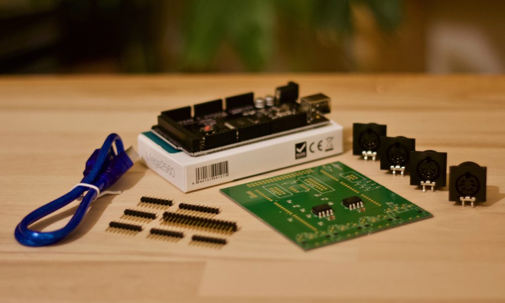
- Mount pin strips
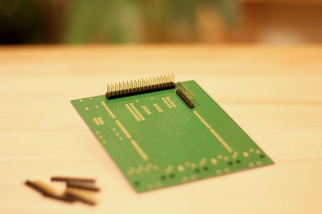
The JORDI board is plugged onto an Arduino Mega. For this it is necessary to mount the enclosed pin headers. The pin headers are inserted through the holes as shown on the photo. Then soldering from above.
2. Mount MIDI-jacks
The enclosed MIDI jacks are inserted through the drilled holes. This requires a bit of sensitivity Don’t use to much force, otherwise the pins will bend over or break off.
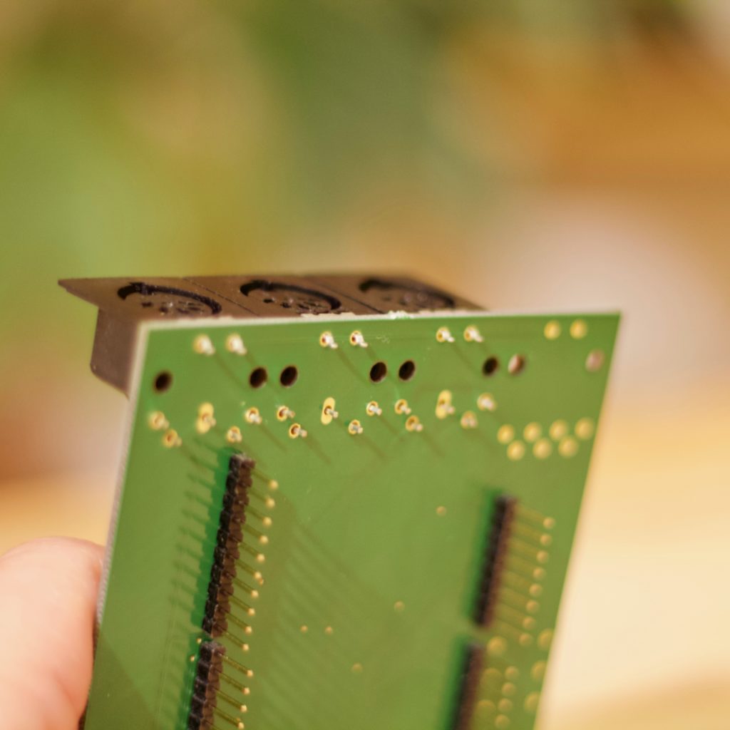
After mounting all 5-pin-MIDI-jacks you have to solder them from below.
If the MFC-101 will be powered up by the JORDI board over an 7-pin-MIDI-cable, an additional step is necessary. For this, the short enclosed 2-wire cable is soldered from the bottom to the Arduino.
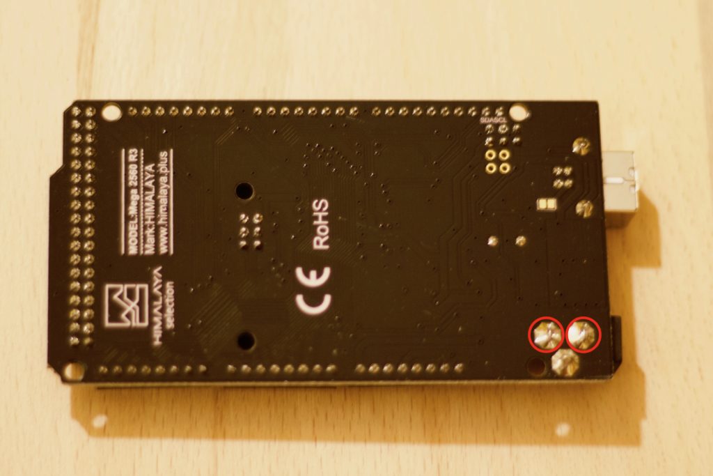
The other stripped ends of the cable are routed through the two marked holes (see photo) of the JORDI board from below. It is not relevant which cable is passed through which hole.
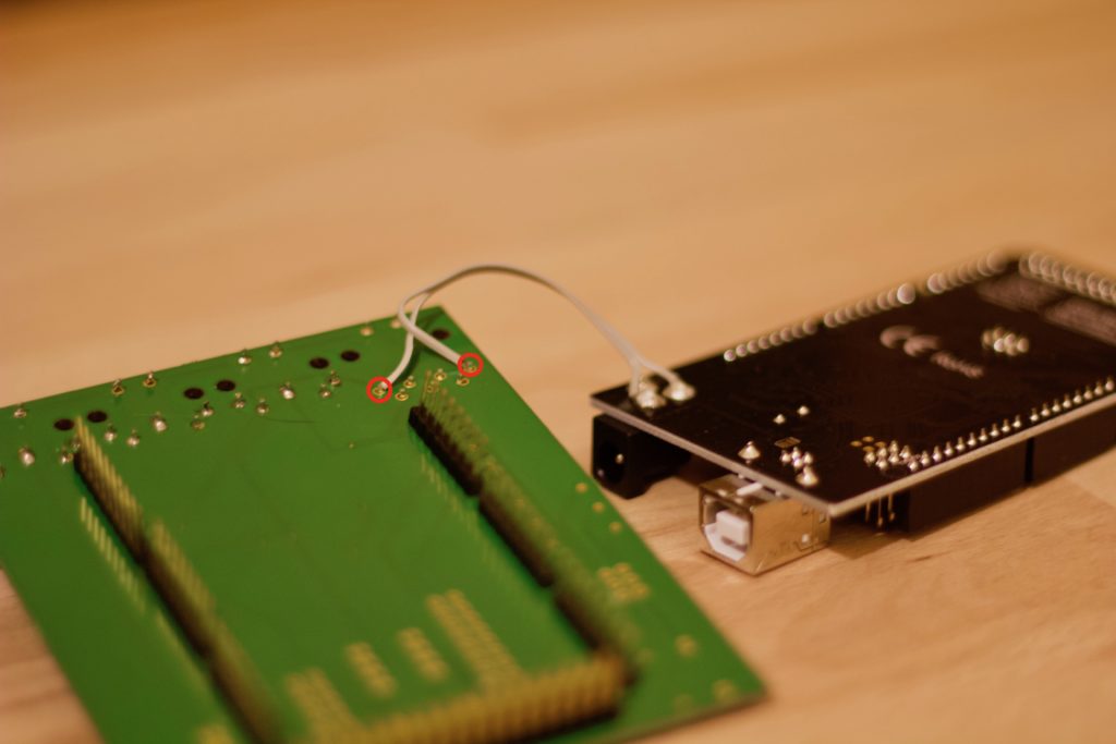
Then insert the 7-pin MIDI jack into the holes from the top without removing the two cables.
Then the contacts are soldered from below.
3. Attach the JORDI board to the Arduino
As a last step, the JORDI board is carefully placed on the Arduino. All pins of the pin headers should be plugged into the Arduino strips. With a little force, the whole thing should be pressed.
Connect the Ax-FX III to the JORDI board
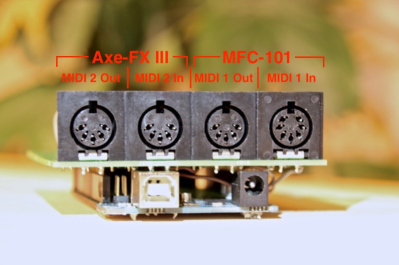
The two MIDI-2 ports of the board are connected to the Ax-FX III by a standard MIDI cable. Two connections are necessary:
- Connect the MIDI-Out of the Ax-FX III to the MIDI-In-2 of the JORDI board
- Connect the MIDI-In of the Ax-FX III to the MIDI-Out-2 of the JORDI board
It’s a good idea to use two short MIDI cables. Place the JORDI board in the rack near the Ax-FX III.
Connect the MFC-101 to the JORDI board
There are several ways to connect the JORDI board to the Ax-FX III and the MFC-101. Depending on what is available for MIDI cables, there are three different types.t
Option 1: With two not fully wired standard MIDI cables
There are many MIDI cables where only three pins of the actual 5 pins are really wired. These cables are intended for one-way communication only. However, as the MFC sends and receives commands, two MIDI cables are required. Here are two connections necessary:
- Connect the MIDI Out of the MFC to the MIDI In 1 of the JORDI board
- Connect the MIDI In of the MFC to the MIDI Out 1 of the JORDI board
Note: The MFC-101 must be powered by the MFC power supply!
Option 2: With a fully wired MIDI cable
Many standard MIDI cables have all 5 pins wired. In this case only one MIDI cable is necessary. Connect the right-most MIDI IN-1 jack of the JORDI board to the MFC-101’s MIDI Out jack.
Note: The MFC-101 must be powered by the MFC power supply!
Option 3: With a fully wired 7-pin MIDI cable
Fully wired 7-pin MIDI cables can be used to provide the MFC-101 with all MIDI data incl. power supply. The JORDI board is built to power up the MFC-101 via a power supply connected to the JORDI board. Connect the rightmost MIDI-In-1 jack of the Jordi board to the MFC-101’s MIDI Out jack.
NOTE: The MFC-101 must NEVER be powered by the MFC power supply!
Another note: The MFC-101 is usually shipped with an AC power adapter. The JORDI board needs a DC power supply and it supplies the MFC-101 with DC power. According to many user reports, this is not a problem (see Wiki), but it may cause problems with longer cable connections. I myself operate the JORDI board with a 5m or 10m 7-pin-MIDI cable without any problems.
The power supply of the MFC-101 is provided by a separate power supply, which is connected to the JORDI board. A power supply with min. 1200 mA/9V is necessary.
Configuration of the Axe-FX III
Some settings are necessary for the MFC to communicate with the Ax-FX III. The following steps describe all the necessary settings:
- Call SETUP by clicking on the parameter “E”-wheel.
- Select MIDI / Remote with the Value wheel and press the ENTER key.
- Set the MIDI channel to 1
- Send “Realtime Sysex” to “ON”.
- Set “Program Change” to “ON”.
- Set “Ignore Redundant PC” to “ON” (not mandatory, but recommended!)
- Set “Send MIDI PC” to “Chan 1”.
Configuration of the MFC-101
For the Axe-FX III to recognize all commands from the MFC-101, the following settings must be made:
- Press EDIT (if necessary press for 3 seconds) to switch to the setup mode of the MFC-101.
- Press button 4 (“MIDI”).
- Set “Use Port” to “MIDI” with the Up / Down buttons.
- Press once on button 7 (“page right”).
- Set “Axe-FX MIDI Ch” to “01” with the Up / Down buttons.
- Press once on button 7 (“page right”).
- Set “Axe-FX TotalSync” to “ON” with the Up / Down buttons.
- Press twice on button 7 (“page right”).
- Set “MIDI Rx Channel” to “01” with the Up / Down buttons.
- Press once on button 7 (“page right”).
- Set “RxProgramChange” to “ON” with the Up / Down buttons.
- Press button 4 (“MIDI”) to return to the setup selection.
- Press button 5 (“SETUP”).
- Set “Axe-FX Mode” to “XL +” with the Up / Down buttons.
- Press the “EDIT” button to save the settings.
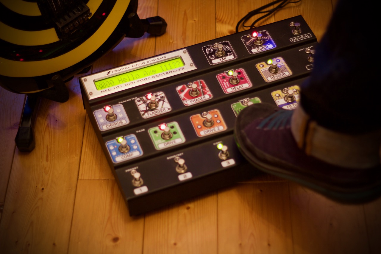
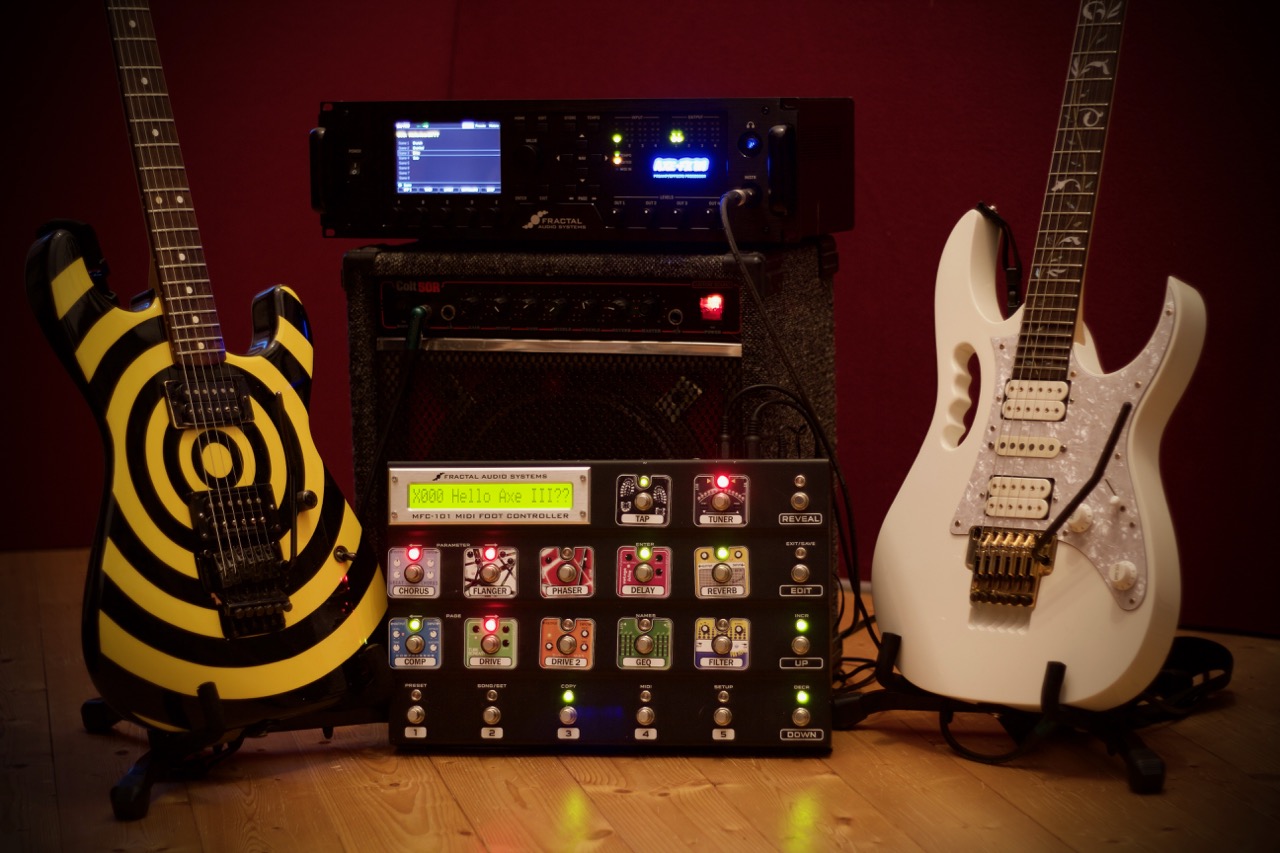
All other settings of the MFC-101 (bank size, assign IA switches, etc.) behave exactly as described in the MFC-101 manual. As soon as the configuration has been completed here and the JORDI board is switched on, the display of the MFC-101 should show the version number of the JORDI firmware (JORDI v1.0). From now on, the MFC-101 will receive all data from the Axe-FX III and will display preset and scene names, tap tempo, tuner, looper status and block status.
Block allocations
The following FX blocks of the MFC are partly interpreted differently in the Axe-FX III because the appropriate blocks no longer exist or have been renamed in the Axe-FX III.
| Axe-FX IA | Axe-III Function |
|---|---|
| Scene 1-8 | Scene 1-8 |
| Scene Inc | – must go directly through CCs – |
| Scene Dec | – must go directly through CCs – |
| Scene 1 / 2 | Scene 1 / 2 |
| Amp 1 | Amp 1 |
| Amp 2 | Amp 2 |
| Cab 1 | Cab 1 |
| Cab 2 | Cab 2 |
| Chorus 1 | Chorus 1 |
| Chorus 2 | Chorus 2 |
| Comp 1 | Comp 1 |
| Comp 2 | Comp 2 |
| Crossover 1 | Crossover 1 |
| Crossover 2 | Crossover 2 |
| Delay 1 | Delay 1 |
| Delay 2 | Delay 2 |
| Drive 1 | Drive 1 |
| Drive 2 | Drive 2 |
| Enhancer | Enhancer |
| Filter 1 | Filter 1 |
| Filter 2 | Filter 2 |
| Filter 3 | Filter 3 |
| Filter 4 | Filter 4 |
| Flanger 1 | Flanger 1 |
| Flanger 2 | Flanger 2 |
| Formant | Formant 1 |
| FX-Loop | Input 3 |
| Gate 1 | Gate 1 |
| Gate 2 | Gate 2 |
| GEQ 1 | GEQ 1 |
| GEQ 2 | GEQ 2 |
| GEQ 3 | GEQ 3 |
| GEQ 4 | GEQ 4 |
| Looper | Looper 1 |
| Megatap | Megatap Delay 1 |
| Mlticmp 1 | Multiband Compressor 1 |
| Mlticmp 2 | Multiband Compressor 2 |
| Mltidly 1 | Multitap Delay 1 |
| Mltidly 2 | Multitap Delay 2 |
| PanTrem 1 | Tremolo/Panner 1 |
| PanTrem 2 | Tremolo/Panner 2 |
| PEQ 1 | PEQ 1 |
| PEQ 2 | PEQ 2 |
| PEQ 1 | PEQ 1 |
| PEQ 2 | PEQ 2 |
| Phaser 1 | Phaser 1 |
| Phaser 2 | Phaser 2 |
| Pitch 1 | Pitch 1 |
| Pitch 2 | Pitch 2 |
| Quad Chorus 1 | Plex Delay 1 |
| Quad Chorus 2 | Plex Delay 2 |
| Resontr 1 | Resonator 1 |
| Resontr 2 | Resonator 2 |
| Reverb 1 | Reverb 1 |
| Reverb 2 | Reverb 2 |
| Ringmod | Ringmod |
| Rotary 1 | Rotary 1 |
| Rotary 2 | Rotary 2 |
| Synth 1 | Synth 1 |
| Synth 2 | Synth 2 |
| Tempo | Tempo |
| Tuner | Tuner |
| Vocoder | Vocoder |
| Volume 1 | Volume 1 |
| Volume 2 | Volume 2 |
| Volume 3 | Volume 3 |
| Volume 4 | Volume 4 |
| Vol Incr | – must go directly through CCs – |
| Vol Decr | – must go directly through CCs – |
| Wha 1 | Wha 1 |
| Wha 2 | Wha 2 |
| Amp 1 XY | Amp 1 Channel A/B |
| Amp 2 XY | Amp 2 Channel A/B |
| Cab 1 XY | Cab 1 Channel A/B |
| Cab 2 XY | Cab 2 Channel A/B |
| Cho 1 XY | Chorus 1 Channel A/B |
| Cho 2 XY | Chorus 2 Channel A/B |
| Dly 1 XY | Delay 1 Channel A/B |
| Dly 2 XY | Delay 2 Channel A/B |
| Drv 1 XY | Drive 1 Channel A/B |
| Drv 2 XY | Drive 2 Channel A/B |
| Flg 1 XY | Flanger 1 Channel A/B |
| Flg 2 XY | Flanger 2 Channel A/B |
| Pha 1 XY | Phaser 1 Channel A/B |
| Pha 2 XY | Phaser 2 Channel A/B |
| Pit 1 XY | Pitch 1 Channel A/B |
| Pit 2 XY | Pitch 2 Channel A/B |
| Rev 1 XY | Reverb 1 Channel A/B |
| Rev 2 XY | Reverb 2 Channel A/B |
| Rot 1 XY | Rotary 1 Channel A/B |
| Rot 2 XY | Rotary 2 Channel A/B |
| Wah 1 XY | Wah 1 Channel A/B |
| Wah 2 XY | Wha 2 Channel A/B |
Switching channels
The Axe-FX III stores four different block settings. These are called Channel A-D. The MFC-101 does not know these channels yet. The firmware of the MFC-101 knows only the X / Y status of a block. This can be used to switch channels A and B of a block.